PRODUCTS
FAult Detector and OScilloscope 9 Functions in 1
FADOS9F1
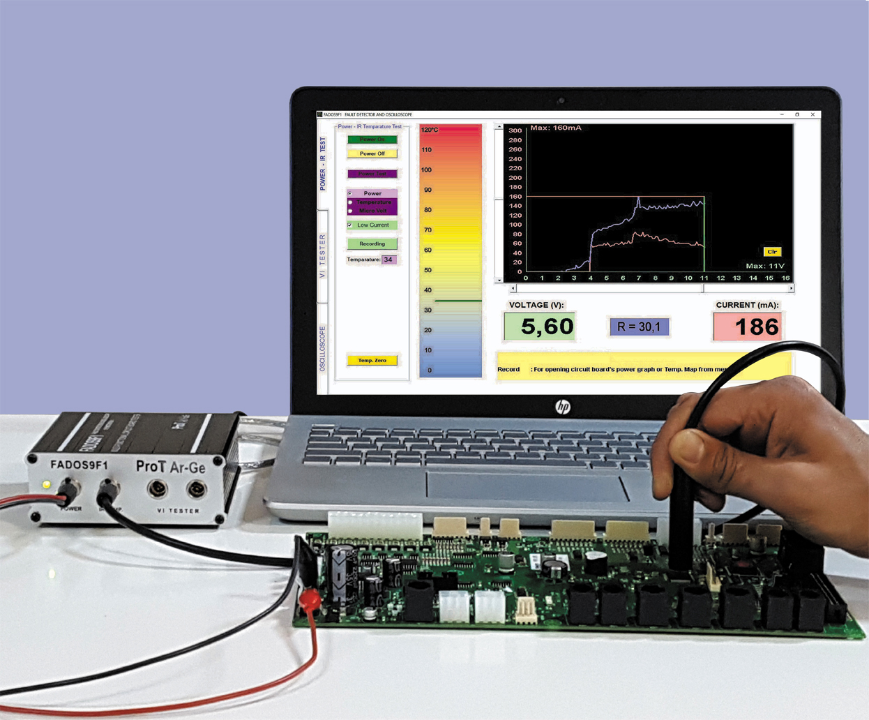
2 unique features are added to the FADOS9F1 over the FADOS71. First feature is the Programmable DC Power Supply; It can be adjusted between 0-16V and 20-1500mA with power output; the DC Voltage/Current graphs of the electronic card power supply can be produced. The second feature is the “IR Remote Temperature Measurement Sensor”; this sensor is used to find the components that heat up by drawing too much current. Using these two features together may reduce the time for trouble shooting some malfunctions by 5 to 10 times. These features can be used as a new technique for trouble shooting.
In this technique, power cable is connected the input of intact board and maximum voltage is adjusted. By pushing the “Power Test” button, the voltage is adjusted from “0” to the desired voltage in 100 mV increments and the voltage-current graph is obtained, which can be recorded when needed. After waiting a few minutes, the temperature map can be obtained by measuring the temperature of the components with the IR sensor.
Then the graph for the intact card is called for testing the defective boards. The maximum current is determined and the supply graph for the defective card is produced. If the defective card draws more current, the temperature of the materials is checked with the IR sensor, allowing to find the material drawing too much current. If the defective card draws less current, this might suggest an open circuit in the supply line. In such a case, the oscilloscope screen is activated to find the areas, where no power is received and to find the broken connection in the line easily. If the defective board produces the same power graph as the intact board, then the VI Tester is activated to find the malfunction.
The FADOS9F1 may be used for Microvolt measurements as well and an output port is provided for attaching a multiplexer. The FADOS products are designed for multiple functions considering all the situations the customer might encounter.
FADOS9F1 Features |
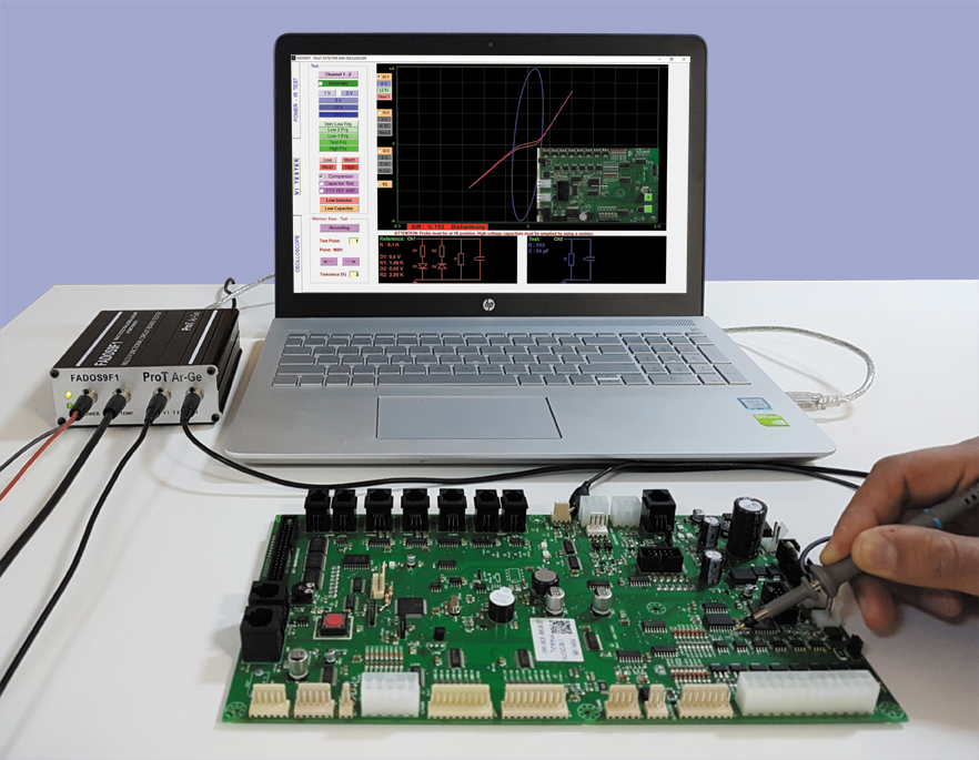
| 1) Dual - Channel Fault Detection by V / T tester (Analog Signature Analyzer - Trouble Shooting) Fault detection by direct comparison of the current-voltage characteristics (signatures) of a working and a faulty circuit board without applying power to the unit under test |
| 2) Fault Detection by Comparison with Stored Signatures (Memory) Signatures of a functioning board can be saved and used at a later time as a reference for troubleshooting a faulty board. The point to touch can be indicated by a cross hair mark at an image of the board. |
| 3) Equivalent Circuit Diagram*** Display of an equivalent circuit that corresponds to the characteristic on the touched point |
| 4) Display Values of Resistor, Capacitor, Inductor and Diode Threshold*** Display the calculated values of resistance, capacitors, inductor and diode threshold voltages corresponding to the conditions at the contacted node |
| 5) Dual - Channel Digital PC Oscilloscope As occasion may require, device can be used as oscilloscope |
| 6) 0.2... 25KHz Square Wave Signal Output Channel 2 is used as a square wave generator. Channel 1 can be used as an oscilloscope |
| 7) Analogue Voltage Output (2,5 mV Sensitivity) Channel 2 is used as Analog DC output -10 V +10 V. Channel 1 can be used as an oscilloscope |
| 8) Programmable Integrated DC Power Supply for Creating Power DC VI Graph**** The output voltage is adjustable. 0 to 16 volts with an output current 20 to 1500 mA, for giving energy to circuit board and creating Power DC Voltage-Current Graph |
| 9) Non Touched IR Temperature Sensor **** To detect more heated components and draw a heat map of the circuit board |
| *** These Functions are Unique Features of 7F1 and 9F1 **** These Functions are New Unique Features of 9F1 |